Mechanical Integrity in Salt Caverns
Salt Cavern Storage in North America
Salt Caverns offer effective means for storage of crude oil, natural gas, NGL, and other hydrocarbon products. They are also a safe and effective way to store or dispose of industrial and oilfield waste. Learn the basics of Salt Caverns →
Along with depleted fields (oil and gas wells that have been emptied), salt caverns are a major component of available underground natural gas storage in North America.
Underground Natural Gas Storage in North America

Underground Natural Gas Storage Sites in North America

Underground Natural Gas Storage Sites in Canada
Underground Gas Storage Capacity in Canada
B.C.
95
Bcf
Alberta
548
Bcf
Saskatchewan
34
Bcf
18 in Salt Caverns
Ontario
267
Bcf
3 in Salt Caverns
Quebec
5
Bcf
Canada
949
Bcf
2.2% in Salt Caverns
What is Mechanical Integrity Testing?
Once developed, testing and maintaining the mechanical integrity of a storage well for both safety and operational efficiency.
A well is generally considered to have mechanical integrity when no significant or measurable leaks from the casing, tubing, or packer can be detected during mechanical integrity testing and there is no fluid movement between formations along the wellbore.
Recompletion or abandonment of wells that do not have mechanical integrity is essential for ensuring containment of stored hydrocarbons within the storage zone.

Salt Cavern Storage

Salt Cavern Storage Mechanical Diagram
Scheduling Mechanical Integrity Tests
When is a Mechanical Integrity Test needed?
Workovers during solution mining if the cause for the workover is a cavern integrity issue.
Prior to commissioning a cavern for storage.
After cavern enlargement.
Workover inspections every 10 years, MIT every five years for both liquid and dry gas cavern operations.
Prior to abandonment.
Unexplained product losses or high pressure in the brine string, indicate that a condition might exist that could adversely affect cavern integrity.
Mechanical Integrity Testing Methods
Nitrogen/Brine Interface (Preferred Method)
Type
Casing Seat Containment Test
Requires
Brine-filled cavern
Opportunities
At end of solution mining, following workovers, or during testing when the cavern is de-inventoried.
Method
Nitrogen gas is injected into a brine-filled cavern to below the casing seat. Movement of the nitrogen-to-brine interface is monitored by wireline log.
The ending amount of nitrogen is compared to the starting amount and assessed against pass/fail criteria.
Nitrogen/Product Interface
Type
Casing Seat Containment Test
Requires
Product over brine-filled cavern
Opportunities
During normal operations or following workover
Method
Nitrogen gas is injected into a product over brine-filled cavern to below the casing seat. Movement of the nitrogen-to-product interface is monitored by wireline log.
The ending amount of nitrogen is compared to the starting amount and assessed against pass/fail criteria.
Product/Brine Interface (Suitable in some instances)
Type
Casing Seat Containment Test
Requires
Product over brine-filled cavern
Opportunities
Following workover.
Method
Liquid product is injected into a brine-filled cavern to below the casing seat. Movement of the product-to-brine interface is monitored by wireline log.
The ending interface level and well pressure is compared to the starting values and assessed against pass/fail criteria.
Liquid Filled
Type
Containment Test
Requires
Liquid-filled cavern at MAOP, known cavern size
Opportunities
When cavern is at MAOP and has been shut in for a suitable time.
Method
Wireline pressure and temperature gauges are lowered into the cavern on two separate dates.
Cavern liquid volume is calculated from data acquired on each log run and the difference in volume is assessed against pass/fail criteria.
Mechanical Integrity Test Procedure — Nitrogen / Brine Interface
Install pressure recorders on annulus and tubing to continuously monitor nitrogen and brine pressures.
Pump brine down tubing to fill cavern. Do not exceed max pressure.
Rig in wireline and log brine interface (pulsed neutron/temperature/CCL/gamma).
Rig in N2 pumper and pressure up annulus with N2. (This pressures up the cavern by displacing brine out of casing and into cavern. Brine string can be bled off to not exceed MAOP)
Log N2 brine interface while filling annulus with N2. Continue to pump N2 until interface depth is in last joint of casing.
Shut-in well, monitor N2 and brine pressures. Continue to log interface for movement (casing pressure check).
Pump N2 and log down interface to casing shoe / cavern top and shut-in well.
Run density/temperature/CCL/gamma to log interface.
Monitor brine and N2 pressures during test duration.
Run density/temperature/CCL/gamma to log interface.
If calculated nitrogen leak rate and minimum detectable leak rate are less than 160 m3/yr (CSA Z341), test is successful. If pressure or temperature stabilization has not been reached, repeat logging / extended testing may be required.
Bleed off pressure, rig out, and release all equipment.
This procedure tests the cavern, the cementing of the casing shoe, the well casing, and the brine string. In addition, this MIT subjects the brine portion of the wellhead to surface brine pressure and the product portion of the wellhead to surface nitrogen pressure.
Interpreting Mechanical Integrity Test Results
The first and last pressure readings and the nitrogen/brine interface depths should be at essentially the same levels to prove cavern integrity.
Although many variables can affect results, a variation of 15 to 30 cm is generally acceptable. 1.0 to 1.2 m generally indicates leak problems.
Typical leak scenarios include:
brine string leaks — brine pressure increases during the test and nitrogen can be detected at the surface in the brine string;
product casing or casing shoe leaks — nitrogen and brine pressure decreases and the interface rises; and
cavern leaks — nitrogen and brine pressure decreases and the interface falls
Interpreting MIT Logs
The N2/Brine Interface Log image below shows a successful MIT test, with the following log curves:
Blue Curve
Cavern and wellbore full of brine prior to starting MIT.
Pink Curve
Start of MIT test showing a nitrogen brine interface.
Green Curve
End of MIT test showing nitrogen brine interface has not moved.
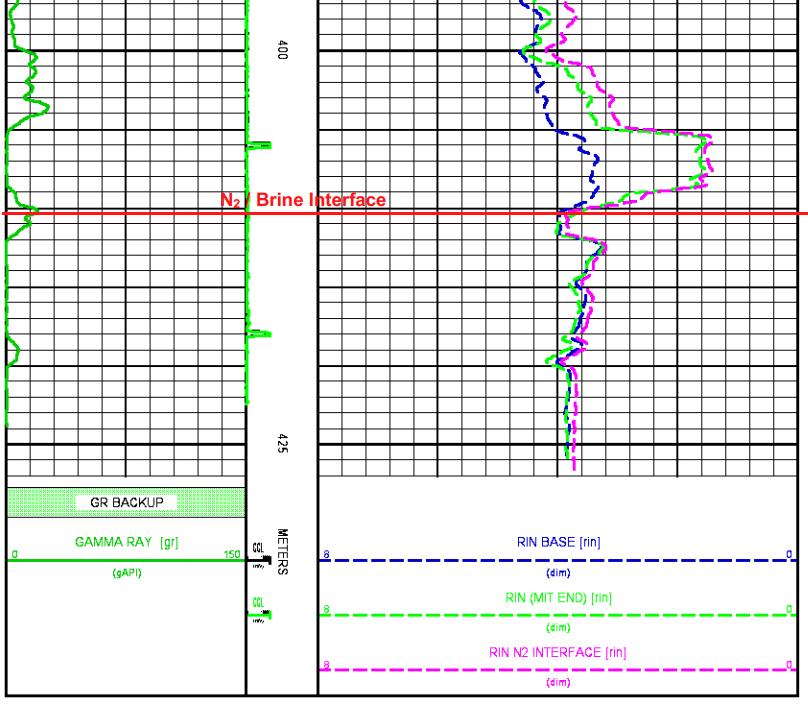
N2/Brine Interface Log